TM 5-3805-262-34
DISASSEMBLY
a.
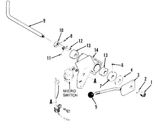
Using paint, put match marks on control lever (3), control shaft (9), and
bracket (14).
b.
Remove lock nut (1) and washer (2).
c.
Remove control lever (3) and washer (4) from control shaft (9) by sliding
off shaft.
d.
If necessary, remove knob (5) from control lever (3).
e. Loosen setscrew (6) and remove collar (7) from control shaft (9).
f.
Carefully pull control shaft (9) with collar (10) attached from bracket
(14). Be careful not to lose spring (11) and spacer (12).
g.
Remove spacer (12) and spring (11).
h.
Loosen setscrew (8) and remove collar (10) from control shaft (9).
NOTE
Do not perform following unless inspection indicates bushings (13) re-
quire replacement.
i.
Remove two bushings (13) from bracket (14) using hammer and drive pin punch.
LEGEND
1. Lock nut
2. Washer
3. Control lever
4. Washer
5. Knob
6. Setscrew
7. Collar
8. Setscrew
9. Control shaft
10. Collar
11. Spring
12. Spacer
13. Bushings (2)
14. Bracket
3-733

