TM 5-3805-262-34
INSTALLATION (SHEET 2 OF 2)
(3)
(4)
(5)
(6)
(7)
(8)
(9)
(lo)
(11)
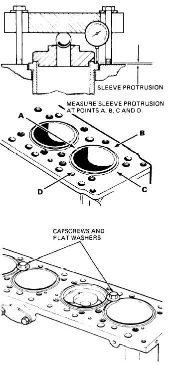
With clamping disk, ball, and
clamp bar positioned, measure
cylinder sleeve (1) protrusion
using dial indicator. Make four
measurements 90 degrees apart
as shown. Sleeve protrusion
must be 0.000 to 0.006 inch.
Replace cylinder sleeve (1) if
protrusion does not meet this
range.
Remove capscrews, clamp bar,
ball, clamping disk, and cylin-
der sleeve (1) from cylinder
block.
Install three new O-rings (2)
on cylinder sleeve (1) bottom
grooves.
Use oil-soluble grease and lu-
bricate three O-rings (2) and
cylinder block lower bore cham-
fer.
Using only the palms of your
hands, push cylinder sleeve (1)
into cylinder block. Install
flat washers and capscrews to
hold cylinder sleeves in
position.
Install camshaft and bearings
(page 4-63).
Install pistons and connecting
rods (page 4-50). Don’t forget
to remove capscrews and washers
holding cylinder sleeves in
position.
Install crankshaft and main
bearings (page 4-26).
Install oil pump (page 3-94).
4-11