
TM 5-3805-290-23-1
HYDRAULIC SYSTEM TESTS, INSPECTIONS, AND ADJUSTMENTS - CONTINUED
0017 00
RELIEF VALVE (LINE) TEST AND ADJUSTMENT - CONTINUED
2.
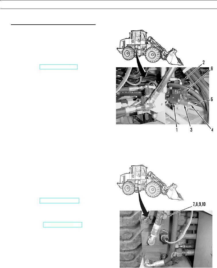
Line Relief Valve for Rod End of Tilt Cylinder.
a.
Remove right chassis cover (WP 0107 00) for
access to combination valve (1).
b.
Connect dial indicating pressure gage to hose.
c.
Connect other end of hose assembly to test port
(6) for rod end of tilt cylinder.
d.
Start engine (TM 5-3805-290-10). Run engine at
high idle. Operate control levers and move all
cylinders to increase temperature of hydraulic oil
to normal operating temperature.
e.
Raise arm to level position. Tilt back work tool
until cylinder rods are fully retracted. Lower arm
until stops for TILT BACK position are engaged.
Slowly lower lift arm. Observe pressure at test
port (6) for rod end of tilt cylinder. As lift arms
lower, linkage pulls rod from cylinders and pres-
sure increases.
f.
Observe gage at test port (6) for relief valve set-
427-B0963
ting and record pressure. Setting for relief valve
should be 4,000 50 psi (27,580 345 kPa).
g.
If line relief valve (7) is not set to correct specifications, lower lift arm to ground. Stop engine (TM 5-3805-290-
10). Adjust line relief valve by preforming steps h and i.
h.
Remove cap (8) from line relief valve (7).
Loosen locknut (9). Turn adjusting screw (10)
clockwise to increase relief valve setting. Turn
adjusting screw counterclockwise to decrease
relief valve setting.
i.
After adjusting screw (10) is adjusted, tighten
locknut (9) to 15 2 lb-ft (20 3 Nm).
j.
Start engine (TM 5-3805-290-10).
k.
Observe pressure gage and record pressure on
gage.
l.
When pressure setting for relief valve is correct,
stop engine (TM 5-3805-290-10) and remove
test equipment.
m.
Install cap (8) on line relief valve (7).
427-B0964-1
0017 00-13