
TM 5-3805-290-23-1
HYDRAULIC SYSTEM TESTS, INSPECTIONS, AND ADJUSTMENTS - CONTINUED
0017 00
RELIEF VALVE (LINE) TEST AND ADJUSTMENT - CONTINUED
3.
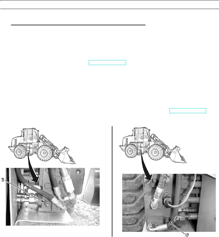
Auxiliary Line Relief Valves for Third Function Hydraulic Arrangement.
a.
Connect dial indicating pressure gage to hose.
N OT E
Test port is at top of bank valve.
b.
Connect other end of hose assembly to test port for piston pump pressure.
c.
Start engine and run engine at low idle (TM 5-3805-290-10).
N OT E
In these steps, DO NOT keep auxiliary control lever in ENGAGED position for more than five seconds
while pressure is at line relief valve setting. This may cause rapid heating of hydraulic oil.
d.
Observe pressure gage and move control lever to ENGAGED position. Position of control lever will depend on
which auxiliary line relief valve is being tested. Pressure setting for head end and rod end of hydraulic tilt cylinder
should be 3,250 50 psi (22,407 346 kPa).
e.
If auxiliary line relief valve (11 or 12) is not set to correct specifications, stop engine (TM 5-3805-290-10). Adjust
line relief valve(s) by performing steps f thru h.
427-B0969
427-B0964-2
0017 00-14