
TM 5-3805-290-23-1
HYDRAULIC SYSTEM TESTS, INSPECTIONS, AND ADJUSTMENTS - CONTINUED
0017 00
PISTON PUMP PRESSURE TEST AND ADJUSTMENT - CONTINUED
8.
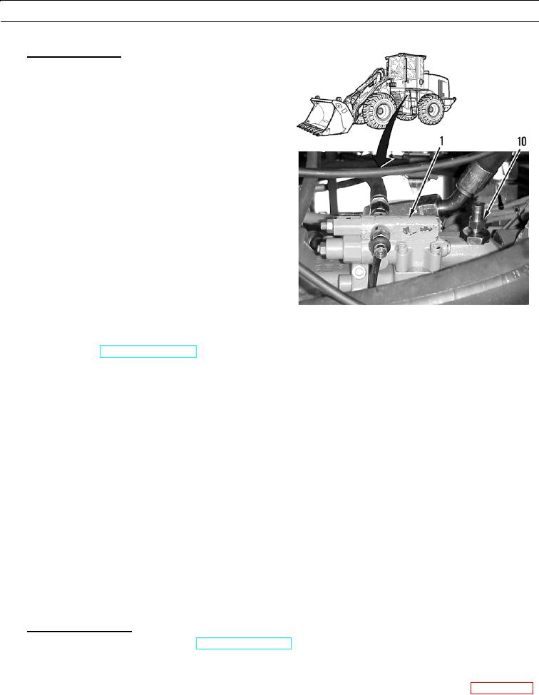
Case Drain Pressure.
N OT E
Only perform this pressure test if exces-
sive internal pump leakage is suspected.
When removing plug for case drain to
install pressure tap, oil must be able to
drain into container.
a.
Remove left chassis covers (WP 0107 00) for
access to piston pumps.
b.
Remove plug from top of piston pump (1) for
work tools.
c.
Install nipple (10) on adapter bushing on port.
d.
Connect pressure gage to hose.
427-B0961
e.
Connect other end of hose assembly to valved nipple assembly.
f.
Start engine (TM 5-3805-290-10).
g.
Run engine at high idle. Operate controls for work tools.
h.
Observe pressure gage. Maximum pressure for case drain is 30 psi (207 kPa). If case drain pressure exceeds 30 psi
(207 kPa), pump has excessive wear or damage. Replace pump (WP 0182 00).
PUMP PERFORMANCE (IMPLEMENT) TEST
0017 00
WARN I N G
Permit only one operator on machine. Keep other personnel away from machine and in sight of operator.
Failure to follow this warning may result in injury or death to personnel.
To prevent possible injury to personnel, perform this procedure before testing and adjusting hydraulic sys-
tem.
N OT E
During diagnosis of hydraulic system, correct oil flow and pressure are necessary for proper machine oper-
ation. Pump output increases as engine speed increases.
When any test is performed on hydraulic system, hydraulic oil must be at normal operating temperature.
Use pressure tests and operational tests to verify cause of symptom. Once cause has been identified, repair
failure and repeat system test.
This procedure should be used to determine if there is a problem with implement pump. Pump perfor-
mance should be checked if machine has slow implement (work tool) movement or low digging power.
Implement Cycle Time.
a.
Relieve hydraulic system pressure (TM 5-3805-290-10).
b.
Speed of implements is affected by amount of oil flow produced by implement pump. Check implement cycle
times to determine if there may be a problem with implement pump.
c.
For information on troubleshooting hydraulic system, refer to Hydraulic System Troubleshooting in WP 0008 00.