4
TM 5-3805-290-23-2
SECONDARY STEERING RELIEF VALVE REPLACEMENT
THIS WORK PACKAGE COVERS
Removal, Installation
INITIAL SETUP
Maintenance Level
References
Unit
Tools and Special Tools
Equipment Conditions
Tool kit, general mechanic's (Item 96, WP 0205 00)
Machine parked on level ground (TM 5-3805-290-
10)
Materials/Parts
Work tool lowered to ground (TM 5-3805-290-10)
Cap set, protective (Item 8, WP 0206 00)
Parking brake engaged (TM 5-3805-290-10)
Oil, lubricating, OEA-30, Arctic (Item 32, WP
Wheels chocked
Oil, lubricating, OE/HDO-5/40 (Item 34, WP 0206
Battery disconnect switch in OFF position (TM 5-
3805-290-10)
Oil, lubricating, OE/HDO-15/40 (Item 35, WP
Steering frame lock connected (TM 5-3805-290-
10)
Rag, wiping (Item 41, WP 0206 00)
Drawings Required
Tag, marker (Item 54, WP 0206 00)
TM 5-3805-290-23P, Figures 89 and 91
O-ring (6)
Estimated Time to Complete Task
Personnel Required
1.0 hr
MOS 62B, Construction Equipment Repairer
WARN I N G
When servicing this machine, performing maintenance, or disposing of hazardous materials, consult your
unit/local hazardous waste disposal center or safety office for local regulatory guidance. If further informa-
tion is needed, please contact The Army Environmental Hotline at 1-800-872-3845.
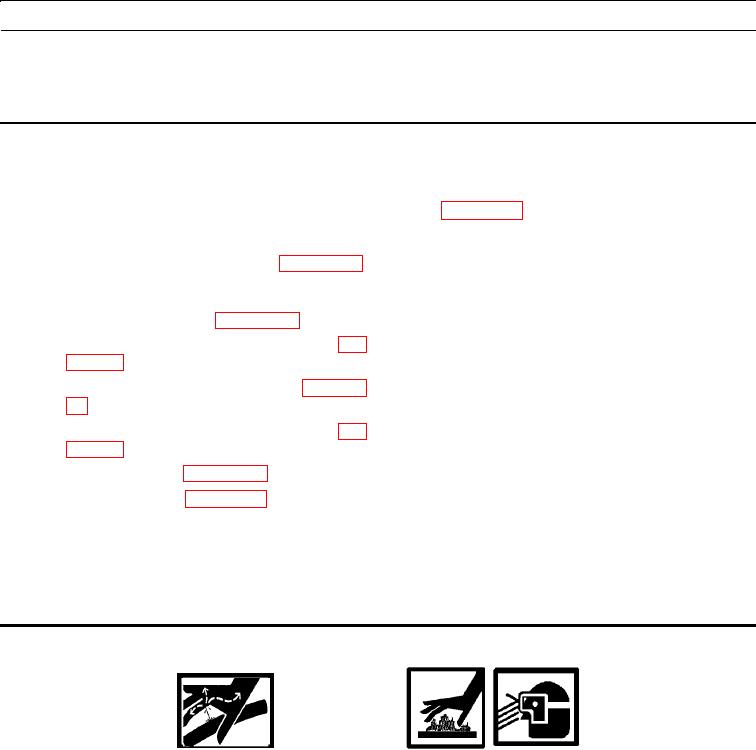
DO NOT disconnect or remove any hydraulic system lines or fitting unless engine is shut down and hydraulic
system pressure has been relieved. Tighten all connections before applying pressure. Escaping hydraulic fluid
under pressure can penetrate the skin, causing injury to personnel.
At operating temperature, hydraulic oil is hot. Allow hydraulic oil to cool before removing any hydraulic fit-
ting. Failure to follow this warning may result in injury to personnel.
To prevent injury to personnel, wear protective eye covering and gloves.
Sudden movement of machine can cause injury to personnel on or near the machine.

