
TM 5-3805-290-23-2
GEAR PUMP BRAKING AND HYDRAULIC FAN REPLACEMENT - CONTINUED
0186 00
INSTALLATION - CONTINUED
N OT E
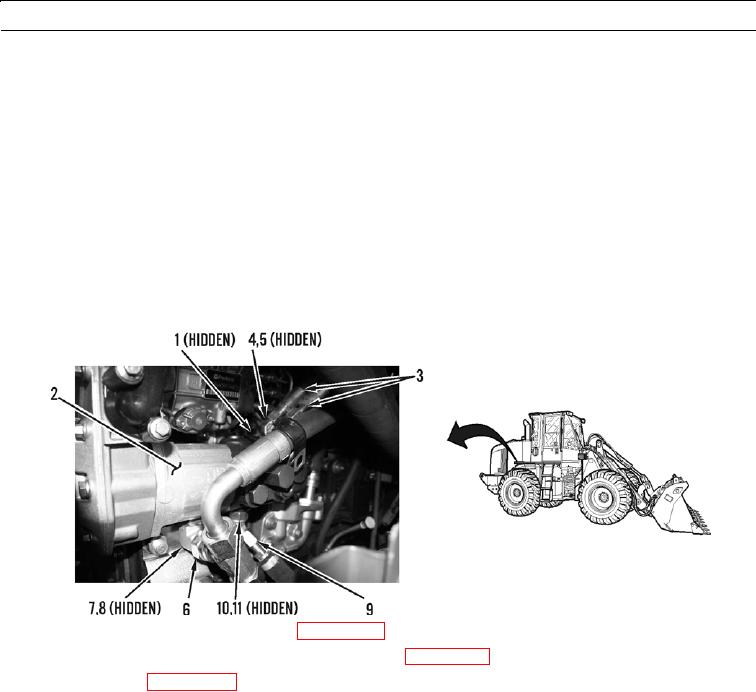
Apply a thin coat of clean oil to all O-rings before installation.
5.
Install two new O-rings (11) and elbow (10) on pump (2).
6.
Connect hose assembly (9) to pump (2).
7.
Install two new O-rings (8) and connector (7) on pump (2).
8.
Connect T (6) to pump (2).
9.
Install four new O-rings (5) and two connectors (4) on pump (2).
10.
Connect two hose assemblies (3) to pump (2).
11.
Connect wiring harness (1) to pump (2).
427-B0732
12.
Connect lower radiator hose to water pump (WP 0045 00).
13.
Install lower right cover between cab and engine access door (WP 0110 00).
14.
Fill hydraulic tank (WP 0137 00).
WAR N I N G
Before operating equipment, secure the steering frame lock in the stowed position. DO NOT operate
machine with steering frame lock connected. Failure to lock steering frame lock into the stowed posi-
tion before operating can result in loss of steering and injury or death to personnel.
15.
Secure steering frame lock in stowed position (TM 5-3805-290-10).
16.
Operate machine to verify normal operation (TM 5-3805-290-10).
17.
Shut down engine (TM 5-3805-290-10).
18.
Check hydraulic oil level (TM 5-3805-290-10).
19.
Check for leaks.
END OF WORK PACKAGE
0186 00-5/(0186 00-6 Blank)