
TM 5-3805-291-10
DESCRIPTION AND USE OF OPERATOR CONTROLS AND INDICATORS - CONTINUED
0004 00
MONITORING SYSTEM
0004 00
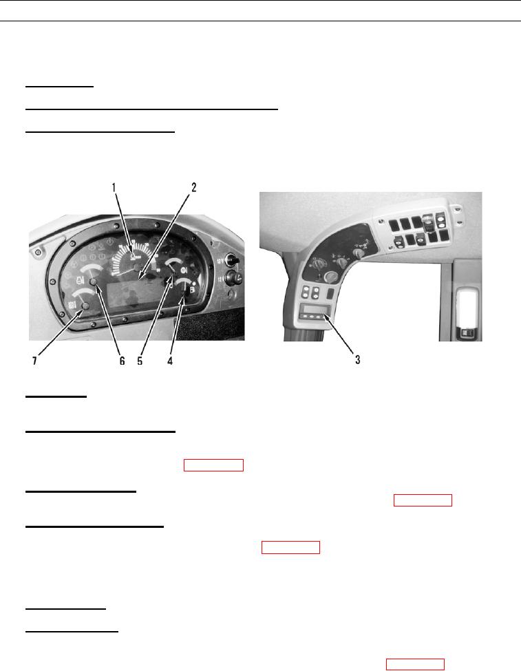
Monitoring systems continuously monitor machine systems. The monitoring system consists of the following displays:
1.
Tachometer (1).
2.
Speedometer, Gear, and Service Meter Digital Display (2).
Messenger Electronic Display (3). Located in the upper-front corner of the cab. Refer to the Messenger Reference
3.
Guide later in this work package.
427-C1974
4.
Fuel Level (4). This gage indicates the amount of fuel in the fuel tank. If the gage needle is in the red zone, the fuel tank
is low on fuel. Refuel the machine as soon as possible.
Transmission Oil Temperature (5). This gage indicates excessive transmission oil temperature. If the gage needle is in
5.
the red area, reduce the load on the machine. If the gage needle is in the red area and if the action light (see callout 15 on
the next page) continues to flash after approximately 5 minutes, stop the machine and investigate the cause of the fault.
Refer to Troubleshooting Introduction (WP 0008 00).
Coolant Temperature (6). This gage indicates excessive coolant temperature. If the gage needle is in the red area, stop
6.
the machine and investigate the cause of the fault. Refer to Troubleshooting Introduction (WP 0008 00).
Hydraulic Oil Temperature (7). This gage indicates excessive hydraulic oil temperature. If the gage needle is in the
7.
red area, reduce the load on the system. If the gage needle remains in the red area, stop the machine and investigate the
cause of the fault. Refer to Troubleshooting Introduction (WP 0008 00).
Front Dash Indicators
1.
Left Turnlamp (8). This indicator illuminates when the left turnlamp is activated.
Primary Steering (9). This indicator illuminates when the oil pressure for the primary steering is low. The indicator
2.
may also indicate a failure of the primary steering. The secondary steering (if equipped) should be automatically acti-
vated. If this alert indicator flashes during operation, stop the machine immediately and engage the parking brake. Stop
the engine and investigate the cause of the fault. Refer to Troubleshooting Introduction (WP 0008 00).