
TM 5-3805-291-23-1
TROUBLESHOOTING WITH A DIAGNOSTIC CODE - CONTINUED
0009 00
Table 4. Implement Control - Continued.
(MID 082)
MALFUNCTION
TEST OR INSPECTION
CORRECTIVE ACTION
427-C1665
N OT E
0490 04
The following test procedure may create other diagnostic codes. Ignore these
created diagnostic codes and clear diagnostic codes when original diagnostic
code is corrected.
Ensure diagnostic code is active.
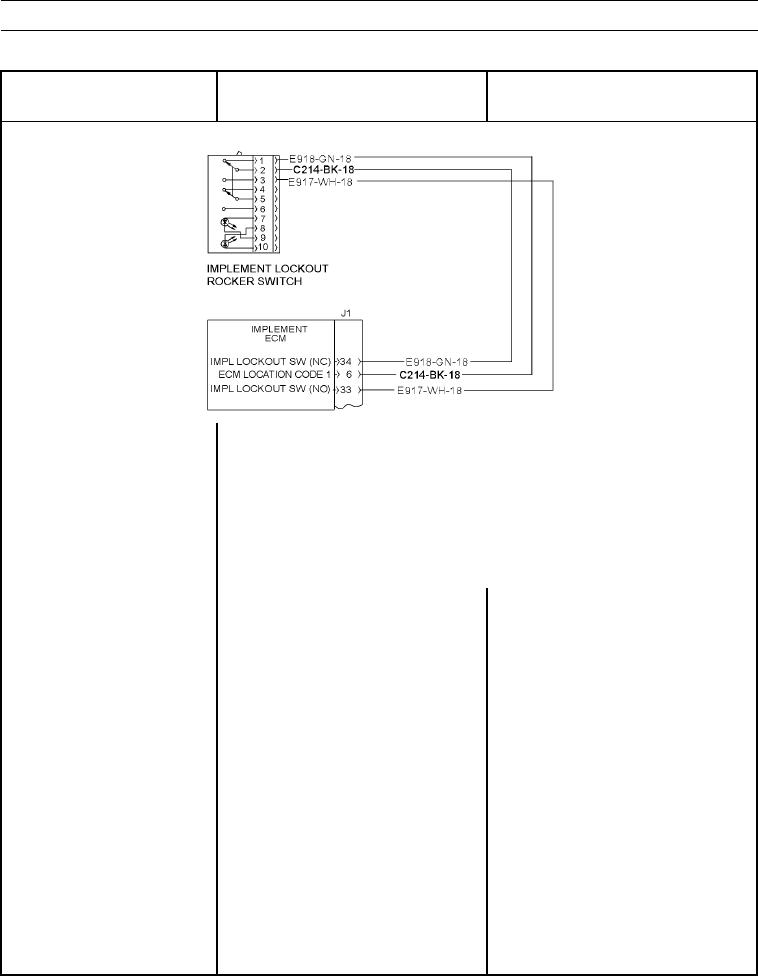
Switch Continuity, Table 5 found at end of this work package, contains wire
numbers and connector contacts. Use this information to troubleshoot failed cir-
cuit.
1. Check switch.
(a) Observe ON/OFF status of
diagnostic code indicator.
(b) Disconnect implement lockout
1. If diagnostic code remains active, go to
switch from wiring harness (WP
Test 2.
0055 00).
2. If diagnostic code is inactive harness has
failed. Repeat this test to verify failure of
switch. Replace joystick (WP 0219 00)
and/or replace wiring harness in question
(WP 0195 00 thru WP 0201 00).
2. Check wiring harness circuit.
(a) This test checks continuity of entire
wiring harness circuit has failed.
This test includes switch that was
previously checked.
(b) Turn battery disconnect switch to
OFF position (TM 5-3805-291-10).