TM 5-3805-291-23-1
BRAKE SYSTEM TESTS, INSPECTIONS, AND ADJUSTMENTS - CONTINUED
0015 00
WARN I N G
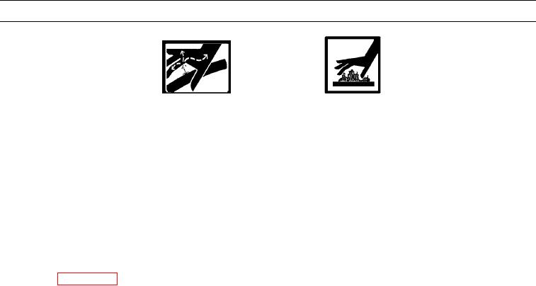
DO NOT disconnect or remove any hydraulic systemline or fitting unless engine is shut down and
hydraulic system pressure has been relieved. Tighten all connections before applying pressure.
Escaping hydraulic fluid under pressure can penetrate the skin, causing injury to personnel.
At operating temperature,hydraulic oil is hot. Allow hydraulic oil to cool before disconnecting
any hydraulic lines. Failure to follow this warning may result in injury to personnel.
N OT E
Tag hoses prior to removal toensure correct installation.
Use a container to catch any fluid that may drainfrom hoses or system. Dispose of fluid IAW local
policy and ordinances. Ensure all spills are cleaned up.
Perform this procedure for on service brake at a time.
e
For a better understanding of each sysem, review the appropriate section in Theory of Operation
t
0015 00
BRAKE SYSTEM AIR PURGE
1.
Remove implement cover (WP 0218 00).
2.
Check oil level in hydraulic oil tank. Maintain correct oil level in hydraulic oil tank throughout air removal procedure
(TM 5-3805-291-10).
3.
Start engine and allow oil pressure to increase to the cut-out pressure.
N OT E
There are two purge screws on top of each axle.
4.
Fasten one end of transparent tube 0.25 in. (6.4 mm) in diameter to one purge screw (1). Place other end of tube into
container for collecting hydraulic oil. Loosen purge screw.
5.
With assistance, slowly press service brake pedal. Hold pedal in this position throughout step 6.
6.
As hydraulic oil flows through tube, check for air bubbles in oil. Allow oil to flow into container until no air bubbles are
visible, then tighten purge screw. Release brake pedal.
7.
Perform this procedure at each purge screw. Make sure to tighten each purge screw.
8.
Check hydraulic oil tank level and fill hydraulic tank if necessary (TM 5-3805-291-10).
9.
If service brake pedal is spongy, repeat steps 5 thru 7.

