TM 5-3805-291-23-1
BRAKE SYSTEM TESTS, INSPECTIONS, AND ADJUSTMENTS - CONTINUED
0015 00
BRAKE CONTROL MANIFOLD TEST - CONTINUED
14.
Repeat steps 5 thru 7.
15.
If further adjustment is necessary, repeat steps 8 thru 13.
If service brake control manifold cut-in and cut-out pressures cannot meet specification, replace service brake control man-
16.
ifold (WP 0217 00).
WARN I N G
Before operating the machine, secure steering frame lock in stowed position. DO NOT operate machine
with steering frame lock connected. Failure to lock steering frame lock into stowed position before operat-
ing can result in loss of steering and injury or death to personnel.
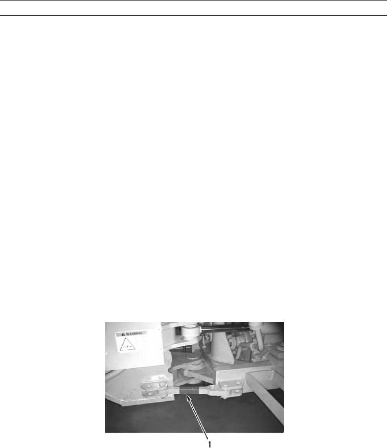
17.
Secure steering frame lock (1) in stowed position (TM 5-3805-291-10).
SERVICE BRAKES SYSTEM PRESSURE TEST
0015 00
WARN I N G
Escaping fluid under pressure, even a pinhole sizeleak, can penetrate body tissue, causing serious
injury, and possible death. If fluid is injected into your skin, it must be treated immediately by a
doctor familiar with this type of injury.
Always use a board or cardbo rd when checking for a leak.
a
Injury or death to personnel can result if two persons are not used in this procedure.
C AU T I O N
Care must be taken to ensure that fluids arecontained during performance of inspection, mainte-
nance, testing, adjusting, and repair of product. Be prepared to collect fluid with suitable contain-
ers before opening any compartment or disassembling any component containing fluids.
Dispose of all fluids accordingto local regulations and mandates.
1.
Connect steering frame lock (1) (TM 5-3805-291-10).
427-C0891
2.
Remove front guard from machine (WP 0132 00).
3.
Depress brake pedal repeatedly in order to release all oil pressure from brake circuit.
4.
Remove protective cap from test port (7) to test oil pressure of rear service brakes.
5.
Install 0 to 2,300 psi (0 to15,850 kPa) pressure gage on test port (7).

