TM 5-3805-291-23-1
BRAKE SYSTEM TESTS, INSPECTIONS, AND ADJUSTMENTS - CONTINUED
0015 00
BRAKE CONTROL MANIFOLD TEST
0015 00
WARN I N G
Escaping fluid under pressure, even a pinhole sizeleak, can penetrate body tissue, causing serious
injury and possible death. If fluid is injected into your skin, it must be treated immediately by a
doctor familiar with this type of injury.
Always use a board or cardbo rd when checking for a leak.
a
Injury or death can result if two p rsons are not used in this procedure.
e
C AU T I O N
Care must be taken to ensure that fluids arecontained during performance of inspection, mainte-
nance, testing, adjusting, and repair of product. Be prepared to collect fluid with suitable contain-
ers before opening any compartment or disassembling any component containing fluids.
Dispose of all fluids accordingto local regulations and mandates.
1.
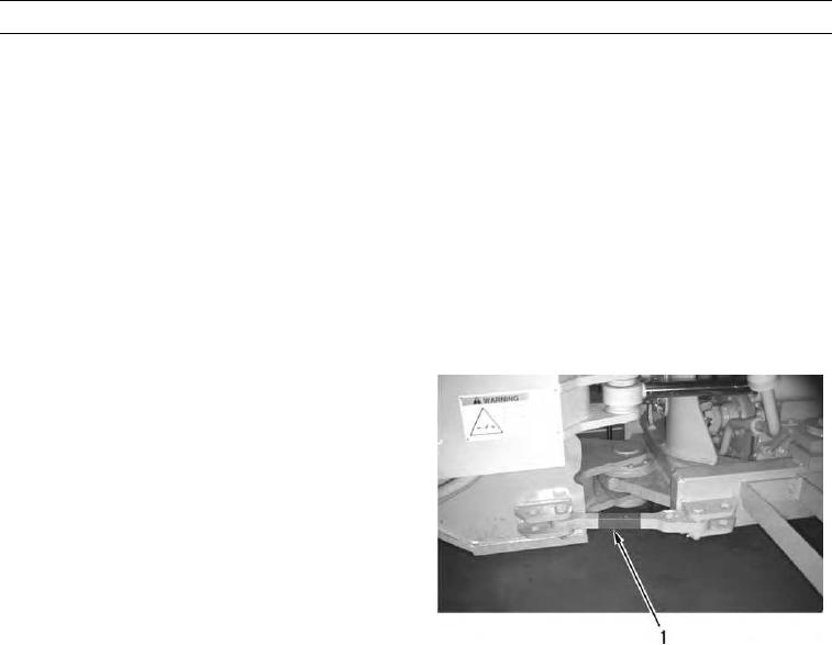
Connect steering frame lock (1) (TM 5-3805-291-10).
2.
Depress brake pedal repeatedly in order to release all
oil pressure from brake circuit.
3.
Remove protective cap from test port (2) to test ser-
vice brake control manifold.
427-C0891
N OT E
Oil pressure must be 0 psi (0 kPa).
4.
Install 0 to 5,800 psi (0 to 40,000 kPa) pressure gage on test port (2).
5.
With assistance, start engine and immediately raise rpm to high idle (TM 5-3805-291-10).
N OT E
Correct service brake control manifoldcut-out pressure should be 2,200 50 psi (15,000 345
kPa).
Oil must increase to maximum. This is the cu-out pressure of the brake accumulator charging
t
valve.
6.
Record highest pressure. This is service brake control manifold cut-out pressure.
N OT E
Correct service brake control manifoldcut-in pressure should be 1,850 50 psi (12,800 345
kPa).
Pressure should drop consistently every time brake pedal is depressed.

