TM 5-3805-291-23-1
BRAKE SYSTEM TESTS, INSPECTIONS, AND ADJUSTMENTS - CONTINUED
0015 00
BRAKE CONTROL MANIFOLD TEST - CONTINUED
7.
With engine running, slowly apply brakes. Apply ser-
vice brakes several times in succession. Verify pres-
sure drops consistently. At this point of specified cut-
in, pressure begins to increase quickly.
N OT E
Perform the following steps if service
brake control manifold cut-in and cut-
out pressures are not within specifica-
tion.
427-C1452
8.
Stop engine (TM 5-3805-291-10).
9.
With assistance, depress brake pedal repeatedly in order to release all oil pressure from brake circuit.
10.
Loosen hydraulic tank filler cap in order to make sure there is no residual pressure in hydraulic oil tank (TM 5-3805-
291-10).
11.
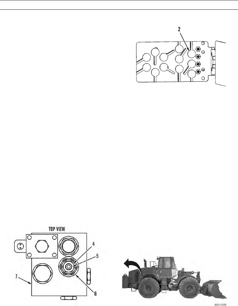
Loosen jamnut (4) on adjustment screw (5).
N OT E
Turning adjustment screw clockwise willincrease service brake control manifold cut-in and cut-
out pressures. Turning adjustment screw counterclockwise will decrease service brake control
manifold cut-in and cut-out pressures.
Range between service brake conrol manifold cut-in and cut-out pressures is not adjustable. Ser-
t
vice brake control manifold cut-in and cut-out pressures move same amount.
Adjust service brake control manifod in quarter-turn increments.
l
12.
Adjust cut-in valve (6) on service brake control manifold (7).
13.
Tighten jamnut (4) on adjustment screw (5).
0015 00-5

