TM 5-3805-291-23-1
BRAKE SYSTEM TESTS, INSPECTIONS, AND ADJUSTMENTS - CONTINUED
0015 00
SERVICE BRAKE WEAR INDICATOR (NEW BRAKE DISC) CHECK
0015 00
WARN I N G
Injury or death can result if two persons are not used in procedure.
C AU T I O N
Care must be taken to ensure that fluids arecontained during performance of inspection, mainte-
nance, testing, adjusting, and repair of product. Be prepared to collect fluid with suitable contain-
ers before opening any compartment or disassembling any component containing fluids.
Dispose of all fluids accordingto local regulations and mandates.
N OT E
When installing new brake discs, you must reco d new measurements for axle's service brake
r
wear indicator. Use this procedure in order to record new measurements. The information will be
recorded in powertrain electronic control module (ECM).
Individual service brakes use in icator pins to determine amount of wear on existing service
d
brake discs. Indicator pins are located on each side of front and rear axle center housings. When
installing new brake discs, you must record these measurements immediately.
Measurements must be recorded for each servce brake containing new brake discs. Measure-
i
ments are used as reference dimensions. Measurements are used to calculate amount of wear for a
given brake disc.
The following steps require accumuator pressure for service brakes:
l
1.
Start and run engine until brake accumulators reach cut-out pressure (less than 30 seconds) (TM 5-3805-291-10).
2.
Stop engine (TM 5-3805-291-10).
3.
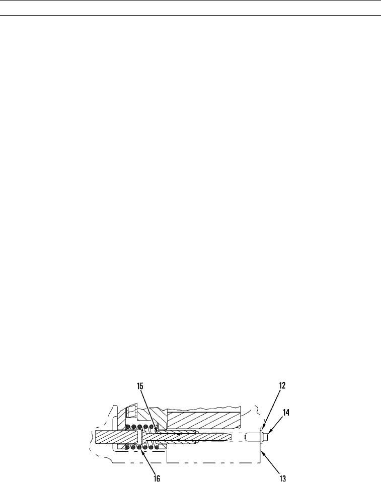
Clean area around plug (12).
4.
Remove excess paint from axle housing flange face (13).
5.
Remove screw (14) and plug (12) from axle housing.
6.
Apply light pressure to pin (15) to ensure pin is seated against cup (16).
427-C0870

