
TM 5-3805-291-23-2
ELECTROHYDRAULIC CONTROL (JOYSTICK) REPLACEMENT - CONTINUED
0219 00
REMOVAL
N OT E
Tag wiring harnesses prior to removal to
ensure correct installation.
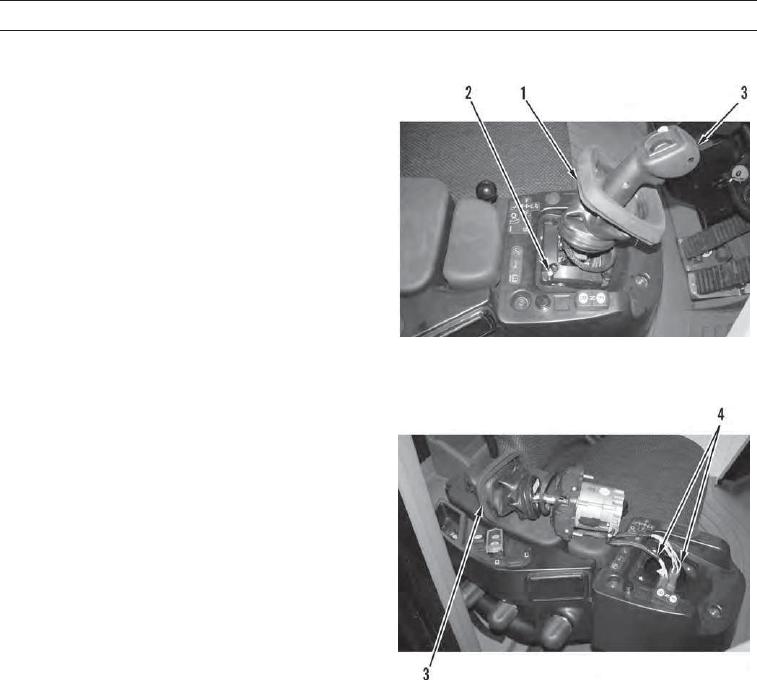
1.
Lift boot (1) high enough to expose four bolts (2) on
electrohydraulic control (3).
2.
Remove four bolts (2) from electrohydraulic control
(3) and position electrohydraulic control as far for-
ward as possible.
427-C0594
3.
Disconnect two wiring harnesses (4).
4.
Remove electrohydraulic control (3) and two wiring
harnesses (4) from machine.
427-C0595
INSTALLATION
1.
Position electrohydraulic control (3) as shown and connect two wiring harnesses (4).
2.
Position electrohydraulic control (3) on machine and install four bolts (2).
3.
Adjust boot (1) to cover four bolts (2) on electrohydraulic control (3).
WAR N I N G
Before operating the machine, secure the steering frame lock in the stowed position. DO NOT operate
machine with steering frame lock connected. Failure to lock steering frame lock into the stowed position
before operating can result in loss of steering and injury or death to personnel.
4.
Secure steering frame lock in stowed position (TM 5-3805-291-10).
5.
Run engine and verify correct operation of electrohydraulic control (TM 5-3805-291-10).
6.
Shut down engine (TM 5-3805-291-10).
END OF WORK PACKAGE
0219 00-2