
TM 5-3805-292-23
0007
HYDROSTATIC SYSTEM CONTINUED
Mechanically Centering Pilot Servo Piston - Continued
0007
26. Disengage parking brake (TM 5-3805-292-10).
WARN I N G
Perform all checks from side of machine. Keep personnel and objects clear of tracks and
tires. Failure to follow this warning may result in injury or death to personnel.
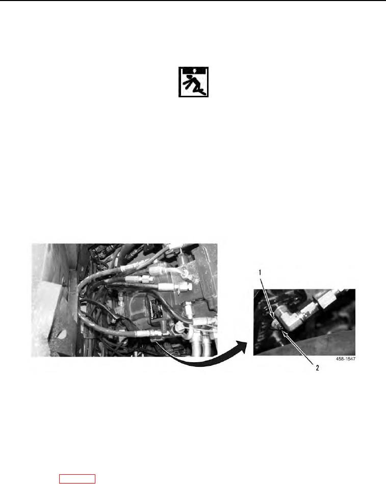
27. Loosen jam nut (Figure 27, Item 1) and turn adjustment screw (Figure 27, Item 2) clockwise until wheels or
tracks begin to move then stop.
28. Mark position of adjustment screw.
29. Rotate adjustment screw counter clockwise until wheels or tracks begin to move in the other direction then
stop.
30. Mark position of adjustment screw.
31. Locate and mark center between both stop points and rotate adjustment screw to center of marks.
32. Reduce engine speed to low idle.
33. Tighten jam nut (Figure 27, Item 1).
Figure 27. Pilot Servo Control Adjustment Screws.
0007
34. Run engine at full throttle (TM 5-3805-292-10). Ensure tracks do not move.
35. If track moves, repeat steps 27 thru 34.
36. Shut down engine.
37. Remove hose and plugs from pilot lines (Figure 27, Item 2) and ports (Figure 27, Item 1) and reconnect pilot
lines.
38. Remove supports and lower machine to the ground.
39. Close ROPS (WP 0134).
END OF TASK
0007-26