
TM 5-3805-292-23
0007
HYDRAULIC SYSTEM CONTINUED
Loader Main Relief Adjustment - Continued
0007
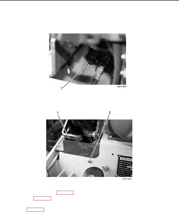
d. Turn screw (Figure 30, Item 1) clockwise to decrease pressure and counter-clockwise to increase pres-
sure.
Figure 30. Loader Main Relief Valve.
0007
e. Install plate (Figure 31, Item 1) and bolt (Figure 31, Item 2).
Figure 31. Access Cover for Adjustment Screw.
0007
f.
Install right joystick console (WP 0105) on machine.
g. Lower ROPS (WP 0134).
10. Repeat steps 3 through 8 until pressure setting is correct.
11. Close ROPS (WP 0134).
END OF TASK