
TM 5-3805-292-23
0007
HYDROSTATIC SYSTEM CONTINUED
Mechanically Centering Pilot Servo Piston - Continued
0007
9. Disengage parking brake (TM 5-3805-292-10).
WARN I N G
Perform all checks from side of machine. Keep personnel and objects clear of tracks and
tires. Failure to follow this warning may result in injury or death to personnel.
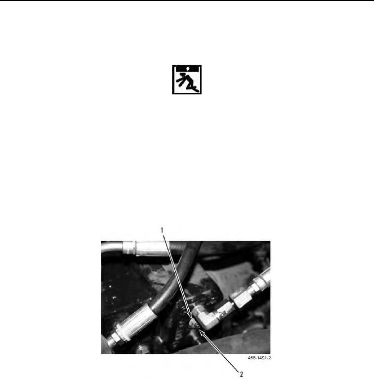
10. Loosen jam nut (Figure 23, Item 1) and turn adjustment screw (Figure 23, Item 2) clockwise until wheels or
tracks begin to move then stop.
11. Mark position of adjustment screw.
12. Slowly, rotate adjustment screw counter clockwise until wheels or tracks begin to move in the other direction
then stop.
13. Mark position of adjustment screw.
14. Locate and mark center between both stop points and rotate adjustment screw to center of marks.
15. Reduce engine speed to low idle.
16. Tighten jam nut (Figure 23, Item 1).
Figure 23. Pilot Servo Control Adjustment Screws.
0007