TM 5-3805-292-23
0007
HYDRAULIC SYSTEM CONTINUED
0007
Loader Main Relief Adjustment - Continued
0007
4. Run engine at full throttle (TM 5-3805-292-10).
5. Actuate auxiliary hydraulic flow control pedal to pressurize hydraulic line with pressure gauge
(TM 5-3805-292-10).
N OT E
Correct main relief pressure is 3,000 50 psi (207 3.5 bar).
Valve is located under right joystick console.
6. Record reading on pressure gauge.
7. Return auxiliary hydraulic flow control pedal to neutral position and decrease engine speed to low idle
(TM 5-3805-292-10).
8. Shut down engine (TM 5-3805-292-10).
9. If pressure is not correct, adjust main relief valve as follows:
a. Tilt ROPS (WP 0134).
b. Position right joystick console (WP 0105) aside.
c.
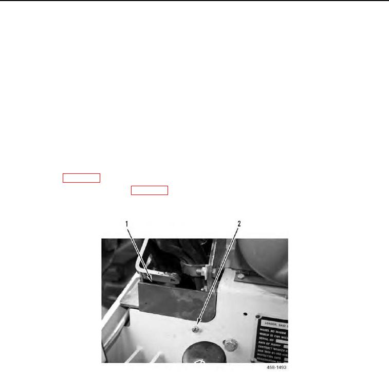
Remove bolt (Figure 29, Item 2) and plate (Figure 29, Item 1).
Figure 29. Access Cover for Adjustment Screw.
0007

