
10
TM 5-3805-292-23
FIELD MAINTENANCE
-
ALTERNATOR REPLACEMENT
0011
ALTERNATOR REMOVAL, MOUNTING BRACKET REMOVAL, DISASSEMBLY, ASSEMBLY,
MOUNTING BRACKET INSTALLATION, ALTERNATOR INSTALLATION
INITIAL SETUP
References
Tools and Special Tools
0
0
Tool Kit, General Mechanic's (WP 0178, Item
TM 5-3805-292-23P, Figure 33
0
33)
0
0
SATS (WP 0178, Item 30)
0
Equipment Conditions
0
Materials/Parts
ROPS tilted (WP 0134)
0
0
Rag, Wiping (WP 0179, Item 19)
Battery power disconnected (WP 0142)
0
0
Tag, Marker (WP 0179, Item 30)
Fan, fan guard, and shroud removed (WP
0
Lockwasher (2)
0
0
O-ring
Machine parked on level ground (TM 5-3805-
0
292-10)
Washers
0
0
Estimated Time to Complete
0
5.4 hr
0
ALTERNATOR REMOVAL
00011
N OT E
Tag wires and electrical connectors to aid in installation.
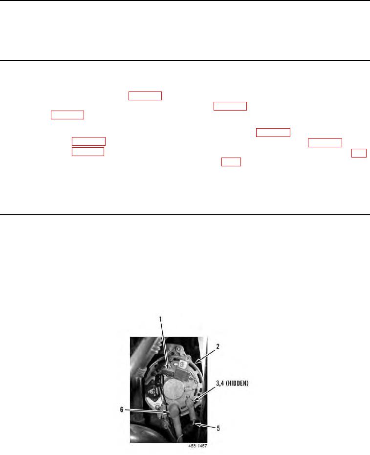
1. Disconnect electrical connector (Figure 1, Item 1) from alternator (Figure 1, Item 2).
2. Position two boots (Figure 1, Item 6) aside and remove two nuts (Figure 1, Item 3), lockwashers (Figure 1,
Item 4) and wires (Figure 1, Item 5) from alternator (Figure 1, Item 2). Discard lockwashers.
Figure 1. Alternator Rear View.
0011