• Home
  • Download PDF
  • Order CD-ROM
  • Order in Print
Figure 5. Alternator.
Figure 7. Engine Oil Cooler Pipe.

Field Maintenance Manual For M400T And M400W
Page Navigation
  166    167    168    169    170  171  172    173    174    175    176  
img
.
TM 5-3805-292-23
0011
MOUNTING BRACKET INSTALLATION
00011
N OT E
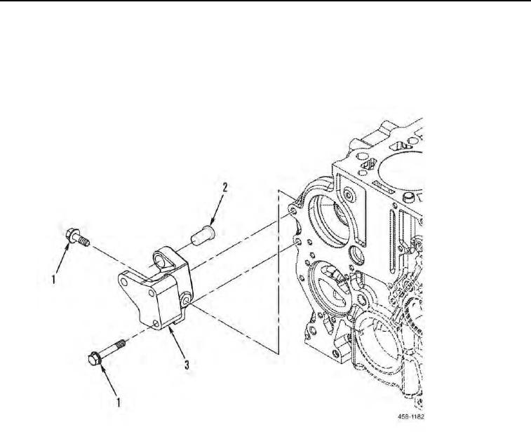
Install bolts as noted during removal.
1. Install spacer (Figure 6, Item 2), bracket (Figure 6, Item 3) and three bolts (Figure 6, Item 1) on machine.
Figure 6. Mounting Bracket Assembly.
0011
0011-6


Privacy Statement
Press Release
Contact

© Copyright Integrated Publishing, Inc.. All Rights Reserved.