Home
Download PDF
Order CD-ROM
Order in Print
Figure 3. Engine Oil Cooler Pipe.
Figure 5. Alternator.
Field Maintenance Manual For M400T And M400W
Page Navigation
164
165
166
167
168
169
170
171
172
173
174
TM
5-3805-292-23
0011
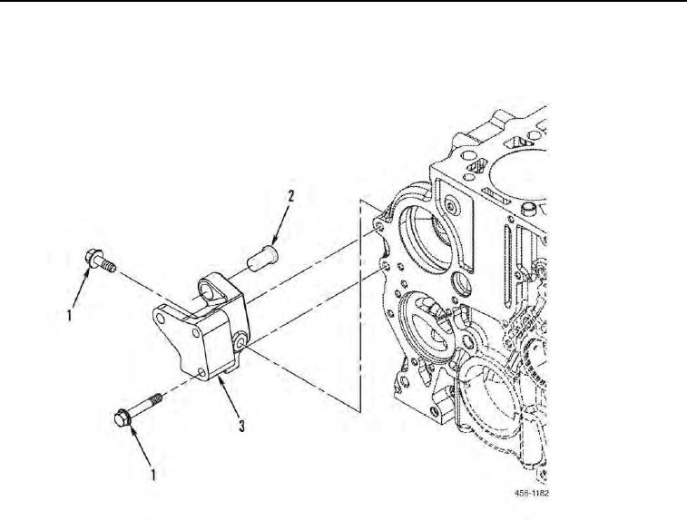
MOUNTING
BRACKET
REMOVAL
CONTINUED
2.
Remove
three
bolts
(Figure
4,
Item
1),
spacer
(Figure
4,
Item
2),
and
mounting
bracket
(Figure
4,
Item
3)
from
machine.
Figure 4. Mounting Bracket
Assembly.
0011
END
OF
TASK
0011-4