• Home
  • Download PDF
  • Order CD-ROM
  • Order in Print
Figure 2. Alternator Front View.
Figure 4. Mounting Bracket Assembly.

Field Maintenance Manual For M400T And M400W
Page Navigation
  163    164    165    166    167  168  169    170    171    172    173  
img
.
TM 5-3805-292-23
0011
MOUNTING BRACKET REMOVAL
00011
N OT E
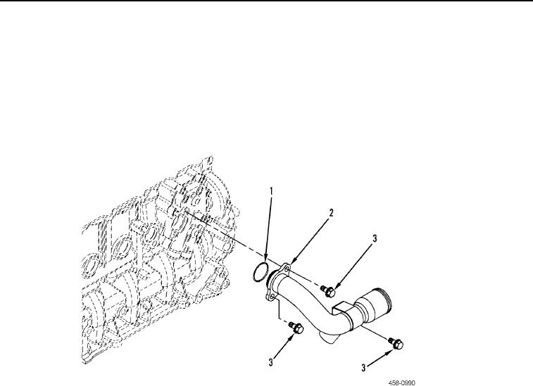
Note size and location of bolts to aid in installation.
Leave hose attached to pipe.
1. Remove three bolts (Figure 3, Item 3), pipe (Figure 3, Item 2), and O-ring (Figure 3, Item 1) from machine. Dis-
card O-ring.
Figure 3. Engine Oil Cooler Pipe.
0011
0011-3


Privacy Statement
Press Release
Contact

© Copyright Integrated Publishing, Inc.. All Rights Reserved.