
TM 5-3805-292-23
0011
DISASSEMBLY
00011
C AU T I O N
Be careful not to damage ribs of pulley. Failure to follow this caution may result in damage
to equipment.
N OT E
Number of spacers may vary.
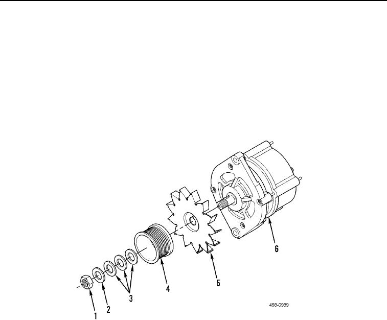
Remove nut (Figure 5, Item 1), washer (Figure 5, Item 2), three spacers (Figure 5, Item 3), pulley (Figure 5, Item
4), and fan (Figure 5, Item 5) from alternator (Figure 5, Item 6).
Figure 5. Alternator.
0011
END OF TASK
ASSEMBLY
00011
Install fan (Figure 5, Item 5), pulley (Figure 5, Item 4), three spacers (Figure 5, Item 3), washer (Figure 5, Item 2),
and nut (Figure 5, Item 1) on alternator (Figure 5, Item 6).
END OF TASK