
TM 5-3805-292-23
0083
INSTALLATION
00083
N OT E
Install all hoses, lines, and fittings as tagged during removal.
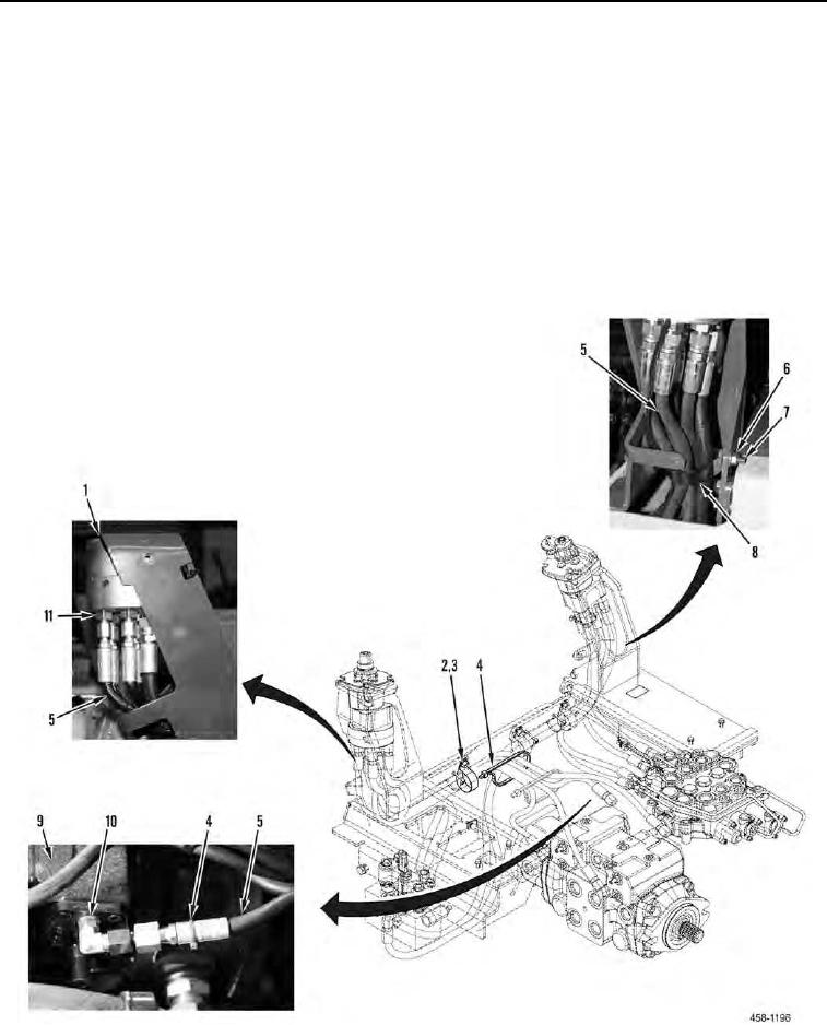
1. Install fitting (Figure 2, Item 10) on pump (Figure 2, Item 9).
2. Install fitting (Figure 2, Item 11) on joystick valve (Figure 2, Item 1).
3. Connect hydraulic hose (Figure 2, Item 5) to fitting (Figure 2, Item 10), and tighten nut.
4. Connect hydraulic hose (Figure 2, Item 5) to fitting (Figure 2, Item 11), and tighten nut.
5. Install two clamps (Figure 2, Item 3) and nuts (Figure 2, Item 2) on hydraulic hose (Figure 2, Item 5).
6. Install clamp (Figure 2, Item 8), bolt (Figure 2, Item 7) and nut (Figure 2, Item 6) on hydraulic hoses (Figure 2,
Item 5).
7. Install new tiedown straps (Figure 2, Item 4) on hydraulic hose (Figure 2, Item 8).
Figure 2. Joystick Hoses and Fittings.
0083
END OF TASK