Home
Download PDF
Order CD-ROM
Order in Print
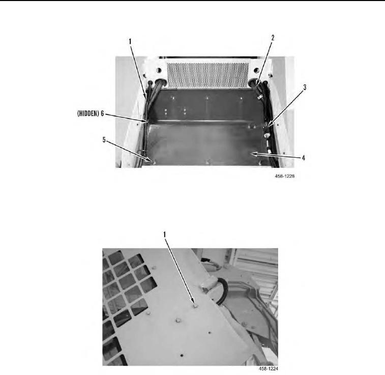
Figure 6. Heat Shield Plate and Brackets.
Figure 9. Heat Shield Plate (Cab Interior).
Field Maintenance Manual For M400T And M400W
Page Navigation
672
673
674
675
676
677
678
679
680
681
682
TM
5-3805-292-23
0099
INSTALLATION
CONTINUED
Figure 7.
Heat
Shield Plate.
0099
7.
Install
two
bolts
(Figure
8,
Item
4) to
plate
(Figure
8,
Item
5).
Figure 8.
ROPS
Bolts.
0099
0099-7