
TM 5-3805-292-23
0127
REMOVAL CONTINUED
10. Remove clamp from bracket and remove control rod from machine.
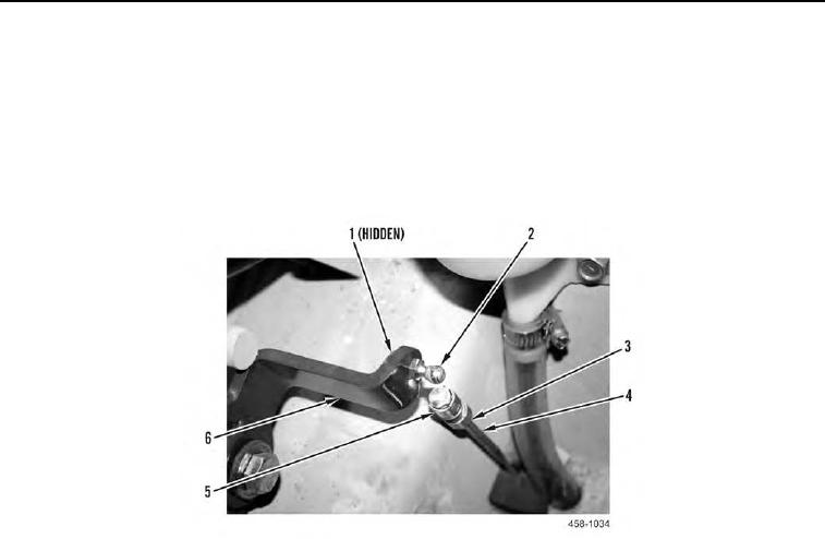
11. Pull back sleeve (Figure 4, Item 5) and remove pedal linkage (Figure 4, Item 4) from ball stud (Figure 4,
Item 2).
12. Remove nut (Figure 4, Item 1) and ball stud (Figure 4, Item 2) from bracket (Figure 4, Item 6).
13. Loosen jam nut (Figure 4, Item 3), and remove sleeve (Figure 4, Item 5) and jam nut (Figure 4, Item 3) from
pedal linkage (Figure 4, Item 4).
Figure 4. Actuator-to-Pedal Linkage (Upper).
0127