
TM 5-3805-292-23
0143
INSTALLATION
000143
N OT E
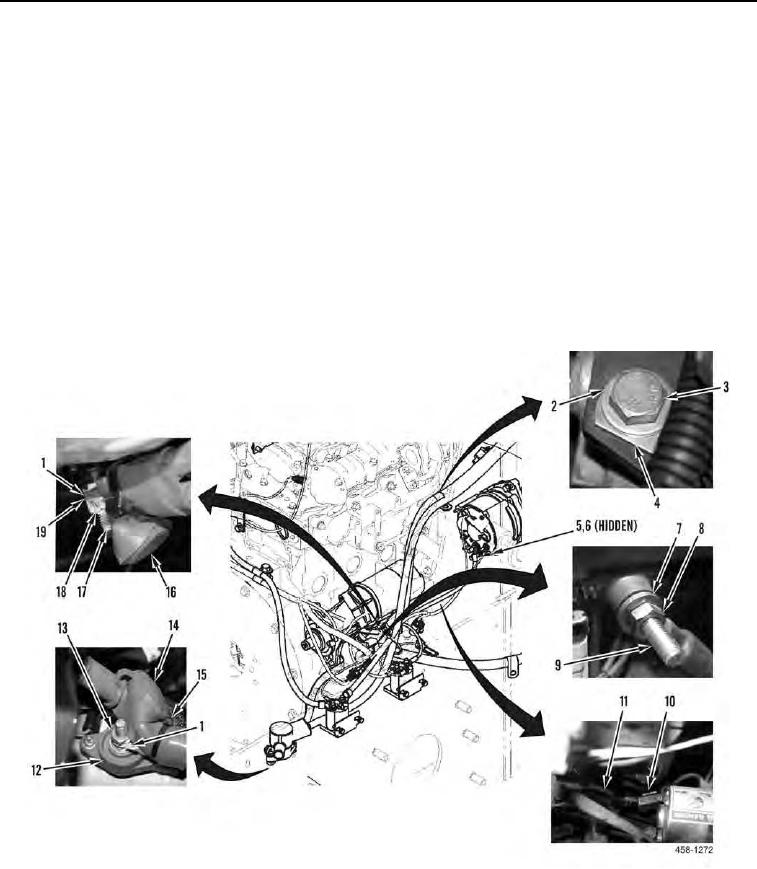
Install battery cables on connection points as tagged during removal.
1. Install cable (Figure 6, Item 11), new lockwasher (Figure 6, Item 6), and nut (Figure 6, Item 5) on alternator.
2. Install two suppressors (Figure 6, Item 10) on cable (Figure 6, Item 11).
3. Install positive battery cable (Figure 6, Item 1), washer (Figure 6, Item 19), nut (Figure 6, Item 18), and cover
(Figure 6, Item 16) on stud (Figure 6, Item 17).
4. Install positive battery cable (Figure 6, Item 1), nut (Figure 6, Item 13), and cover (Figure 6, Item 14) on single-
point power distribution block (Figure 6, Item 12).
5. Install negative battery cable (Figure 6, Item 7) and nut (Figure 6, Item 8) on engine ground stud (Figure 6,
Item 9).
6. Install four clamps (Figure 6, Item 4), washers (Figure 6, Item 2), and bolts (Figure 6, Item 3) on machine.
7. Install new tiedown straps (Figure 6, Item 15) on positive battery cables (Figure 6, Item 1).
Figure 6. Battery Cables and Single-Point Power Distribution Block.
0143