
TM 5-3805-292-23
0143
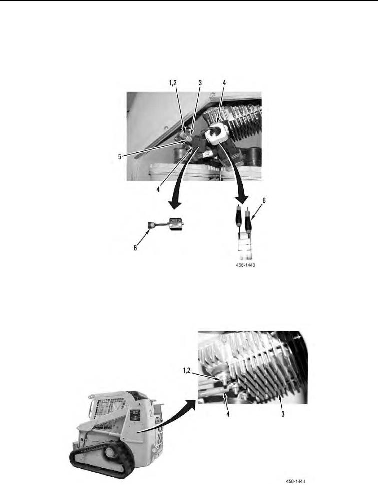
REMOVAL CONTINUED
8. In battery compartment, remove 10 suppressors (Figure 2, Item 4) from machine. Use screwdriver (Figure 2,
Item 6) to release suppressor (Figure 2, Item 4).
9. Remove two bolts (Figure 2, Item 1), lockwashers (Figure 2, Item 2), and cable (Figure 2, Item 5) from NATO
plug (Figure 2, Item 3). Discard lockwashers.
Figure 2. NATO Plug Connection.
0143
10. Remove three nuts (Figure 3, Item 1), lockwashers (Figure 3, Item 2), and cables (Figure 3, Item 4) from power
equalizer (Figure 3, Item 3). Discard lockwashers.
Figure 3. Power Equalizer Connection.
0143