
TM 5-3805-292-23
0143
INSTALLATION CONTINUED
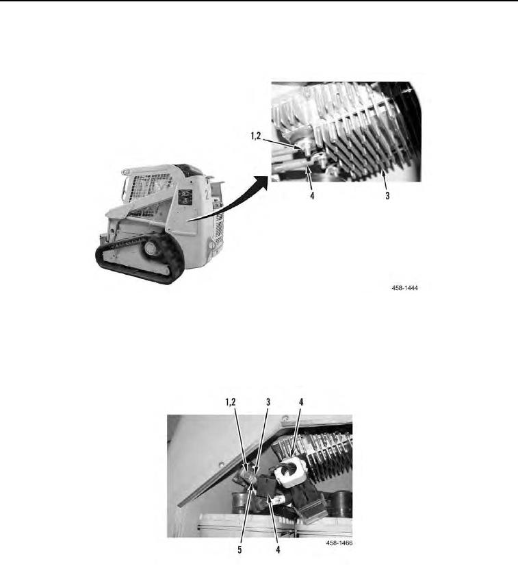
10. Position three cables (Figure 9, Item 4) and install three new lockwashers (Figure 9, Item 2) and nuts (Figure 9,
Item 1) on power equalizer (Figure 9, Item 3).
Figure 9. Power Equalizer Connections.
0143
11. In battery compartment, install cable (Figure 10, Item 5), two new lockwashers (Figure 10, Item 2), bolts (Fig-
ure 10, Item 1) on NATO plug (Figure 10, Item 3).
12. Install 10 suppressors (Figure 10, item 4) on machine.
Figure 10. NATO Plug Connection.
0143
END OF TASK