• Home
  • Download PDF
  • Order CD-ROM
  • Order in Print
Figure 6. Battery Cables and Single-Point Power Distribution Block.
Figure 9. Power Equalizer Connections.

Field Maintenance Manual For M400T And M400W
Page Navigation
  949    950    951    952    953  954  955    956    957    958    959  
img
.
TM 5-3805-292-23
0143
INSTALLATION CONTINUED
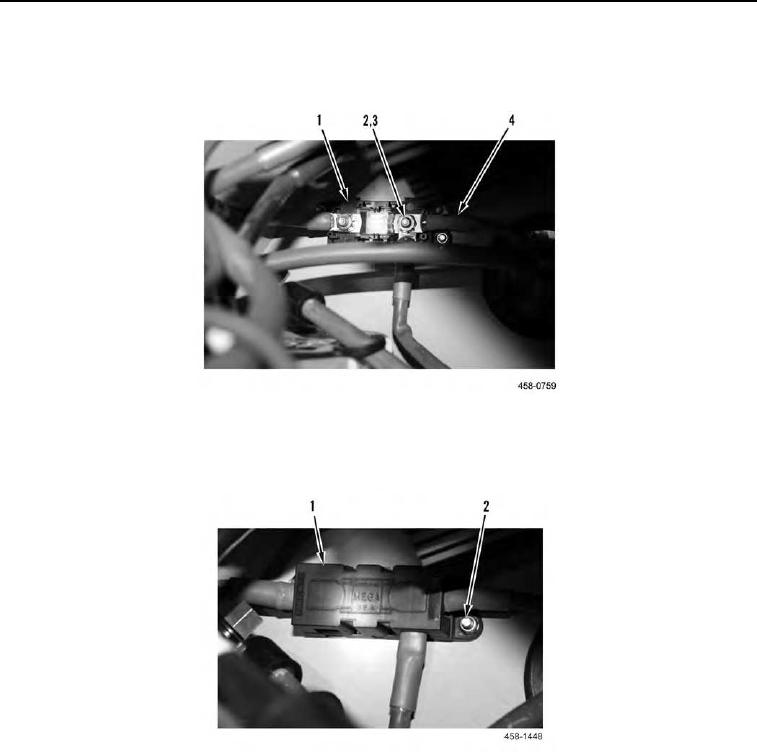
8. Position three cables (Figure 7, Item 4) and install two star washers (Figure 7, Item 3) and nuts (Figure 7,
Item 2) on 100 amp fuse (Figure 7, Item 1).
Figure 7. 100 Amp Fuse.
0143
9. Install cover (Figure 8, Item 1) on 100 amp fuse (Figure 8, Item 2).
Figure 8. 100 Amp Fuse.
0143
0143-6


Privacy Statement
Press Release
Contact

© Copyright Integrated Publishing, Inc.. All Rights Reserved.