
TM 5-3805-292-23
0146
REMOVAL CONTINUED
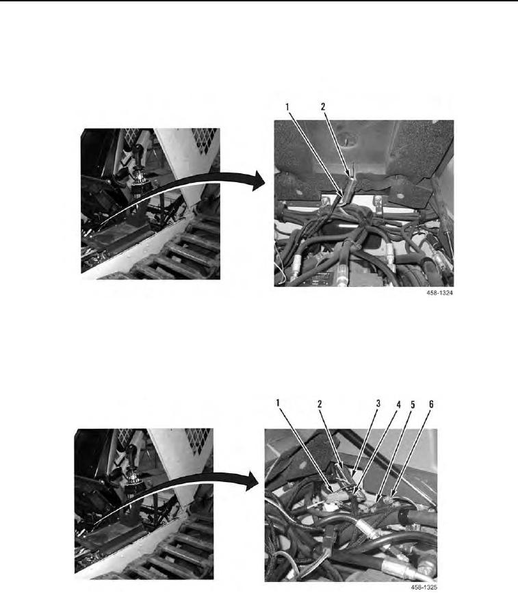
33. Disconnect harness connector (Figure 14, Item 1) from occupant presence switch pigtail (Figure 14, Item 2).
Figure 14. Occupant Presence Switch Connection.
0146
34. Disconnect harness connector (Figure 15, Item 1) from right hand joystick pigtail (Figure 15, Item 4).
35. Disconnect harness connector (Figure 15, Item 3) from right hand joystick pigtail (Figure 15, Item 2).
36. Disconnect three harness connectors (Figure 15, Item 5) from harness connectors (Figure 15, Item 6).
Figure 15. Right Hand Joystick Connection.
0146