
TM 5-3805-292-23
0146
REMOVAL CONTINUED
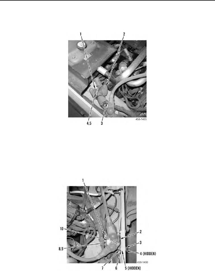
37. Remove boot (Figure 16, Item 2), nut (Figure 16, Item 4), lockwasher (Figure 16, Item 5) and two cables (Fig-
ure 16, Item 3) from single point power distribution block (Figure 16, Item 1). Discard lockwasher.
Figure 16. Single Point Power Distribution Block Connection.
0146
38. Remove wire (Figure 17, Item 2) from grid heater relay (Figure 17, Item 1).
39. Remove nut (Figure 17, Item 9), washer (Figure 17, Item 8), and wire eyelet (Figure 17, Item 10) from grid
heater relay (Figure 17, Item 1).
40. Remove two nuts (Figure 17, Item 7), washers (Figure 17, Item 6), bolts (Figure 17, Item 3), washers (Figure
17, Item 4), washers (Figure 17, Item 5) and position grid heater relay (Figure 17, Item 1) aside.
Figure 17. Single Point Power Distribution Block Connection.
0146