
TM 5-3805-292-23
0146
INSTALLATION CONTINUED
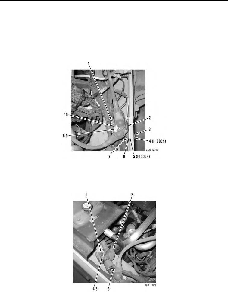
4. Position two washers (Figure 21, Item 5) and grid heater relay (Figure 21, Item 1) on frame.
5. Install two washers (Figure 21, Item 4), two bolts (Figure 21, Item 3), two washers (Figure 21, Item 6), and two
nuts (Figure 21, Item 7) on grid heater relay (Figure 21, Item 1).
6. Install wire eyelet (Figure 21, Item 10), washer (Figure 21, Item 8), and nut (Figure 21, Item 9) on grid heater
relay (Figure 21, Item 1).
7. Install wire (Figure 21, Item 2) on grid heater relay (Figure 21, Item 1).
Figure 21. Single Point Power Distribution Block Connection.
0146
8. Install two cables (Figure 22, Item 3), new lockwasher (Figure 22, Item 5), nut (Figure 22, Item 4), and boot
(Figure 22, Item 2) on single point power distribution block (Figure 22, Item 1).
Figure 22. Single Point Power Distribution Block Connection.
0146