
TM 5-3805-292-23
0146
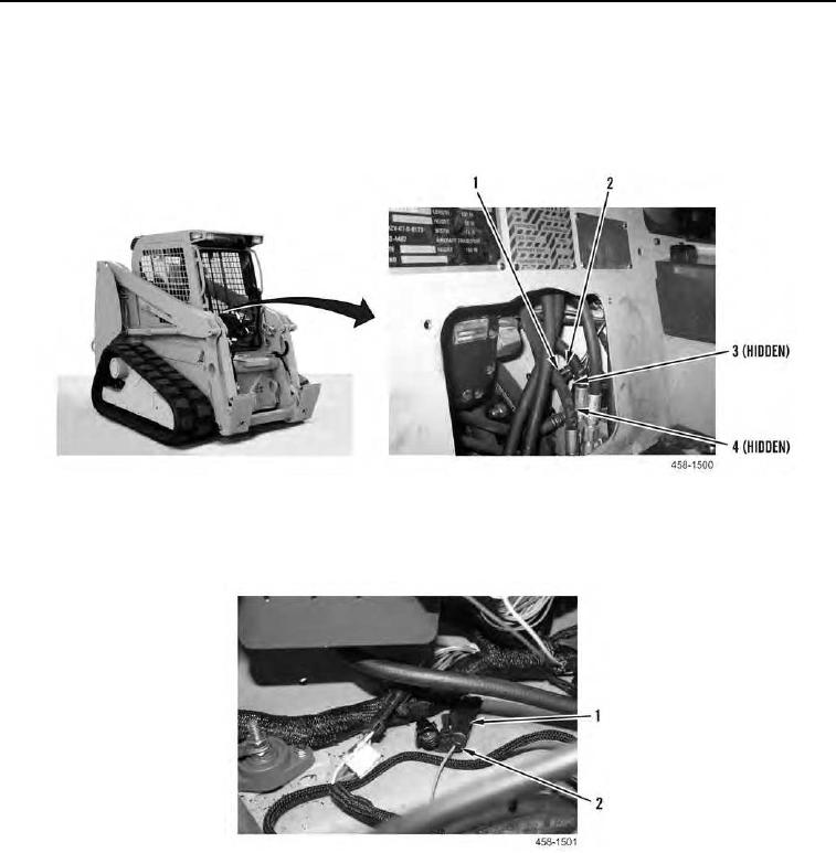
REMOVAL CONTINUED
30. From inside the cab, disconnect harness connector (Figure 12, Item 2) from brake pilot valve solenoid (Figure
12, Item 1).
31. From inside the cab, disconnect harness connector (Figure 12, Item 3) from brake pilot valve sensor pigtail
(Figure 12, Item 4).
Figure 12. Brake Pilot Valve Connections.
0146
32. Disconnect two connectors (Figure 13, Item 1) from chassis harness (Figure 13, Item 2).
Figure 13. Chassis Harness Connections.
0146