
TM 5-3805-292-23
0146
INSTALLATION CONTINUED
13. Connect two connectors (Figure 25, Item 1) to chassis harness (Figure 25, Item 2).
Figure 25. Chassis Harness Connections.
0146
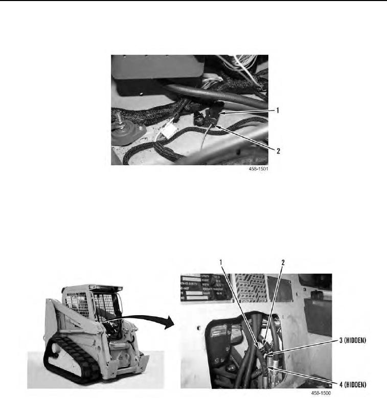
14. From inside cab, connect harness connector (Figure 26, Item 1) to brake pilot valve sensor pigtail (Figure 26,
Item 2).
15. From inside cab, connect harness connector (Figure 26, Item 4) to brake pilot valve solenoid (Figure 26, Item
3).
Figure 26. Brake Pilot Valve Connections.
0146