
TM 5-3805-292-23
0146
INSTALLATION CONTINUED
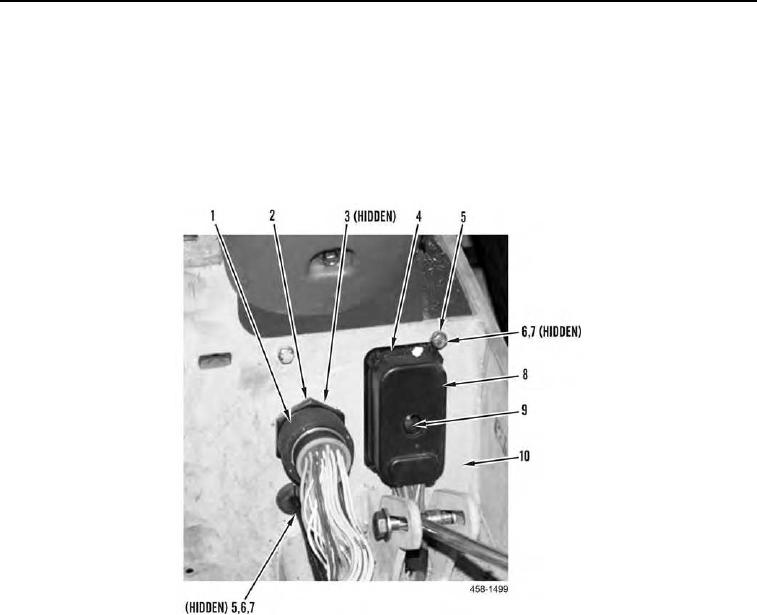
16. Install bulkhead connector (Figure 27, Item 3) and nut (Figure 27, Item 4) to bulkhead (Figure 27, Item 10).
17. Connect cannon plug (Figure 27, Item 1) to bulkhead connector (Figure 27, Item 3).
18. Install harness bulkhead connector (Figure 27, Item 4), two washers (Figure 27, Item 6), bolts (Figure 27, Item
5), and two nuts (Figure 27, Item 7) on bulkhead (Figure 27, Item 10).
19. Connect harness connector (Figure 27, Item 8) to chassis harness bulkhead connector (Figure 27, Item 4) and
tighten bolt (Figure 27, Item 9).
Figure 27. Left Joystick Support Connection.
0146