
TM 5-3805-292-23
0169
ASSEMBLY CONTINUED
Hoses - Continued
000169
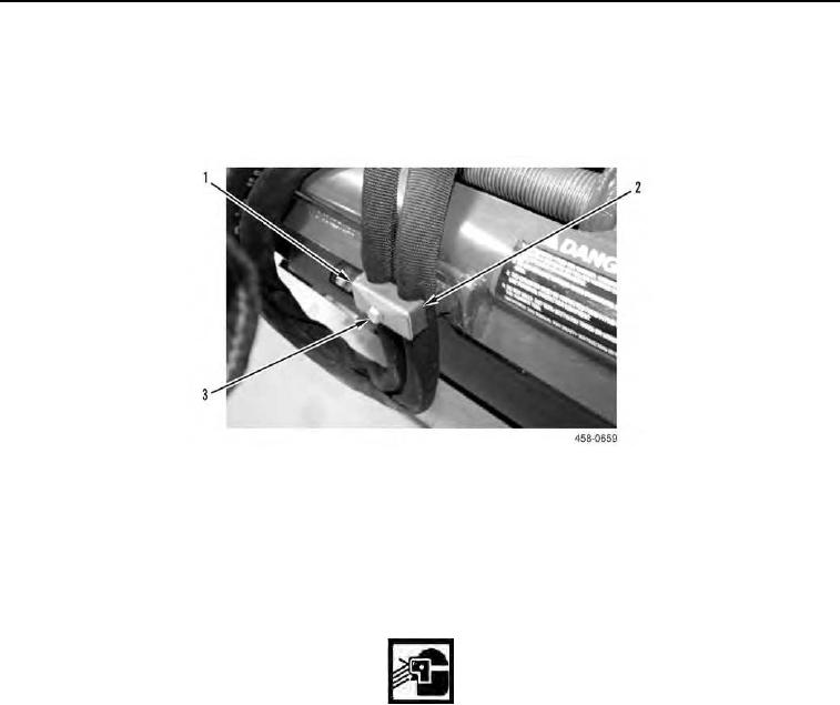
2. Position hose cushion (Figure 10, Item 2) on assembly and install plate (Figure 10, Item 1) and bolt (Figure 10,
Item 3).
Figure 10. Hose Cushion.
0169
END OF TASK
NITROGEN DISCHARGING/CHARGING
000169
Discharging Hammer
000169
WARN I N G
System is under pressure.
N OT E
Cap all hoses and plug all openings.
0169-8