
TM 5-3805-292-23
0171
DISASSEMBLY CONTINUED
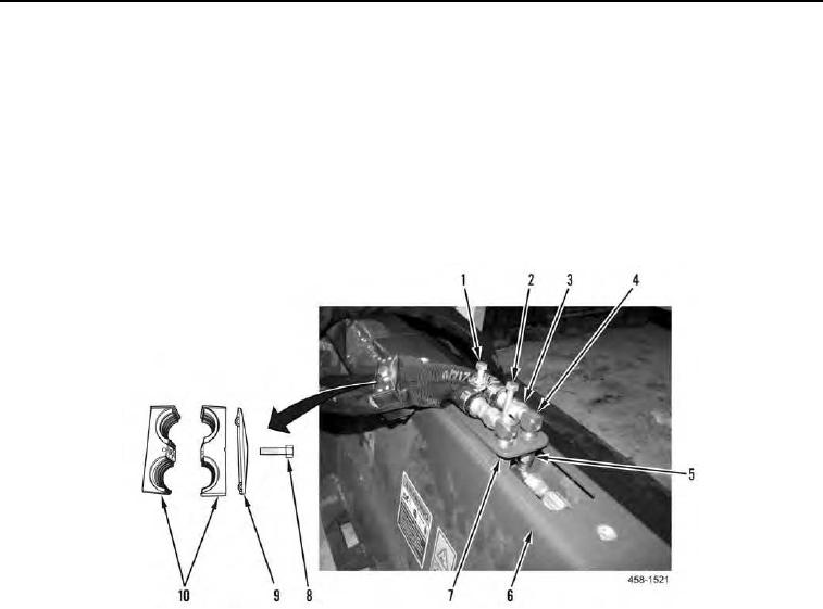
4. Remove capscrew (Figure 2, Item 8), plate (Figure 2, Item 9), and hose cushion (Figure 2, Item 10) from back
blade (Figure 2, Item 6).
5. Tighten capscrew (Figure 2, Item 1), and install capscrew (Figure 2, Item 2) on hydraulic plate (Figure 2, Item
7).
6. Disconnect two hoses (Figure 2, Item 3) from two 90 elbows (Figure 2, Item 4).
7. Disconnect two tees (Figure 2, Item 5) from two 90 elbows (Figure 2, Item 4).
8. Remove capscrews (Figure 2, Items 1 and 2) from hydraulic plate (Figure 2, Item 7). Remove hydraulic plate
(Figure 2, Item 7) with 90 elbows from assembly.
Figure 2. Bucket Hoses.
0171