
TM 5-3805-292-23
0170
ASSEMBLY CONTINUED
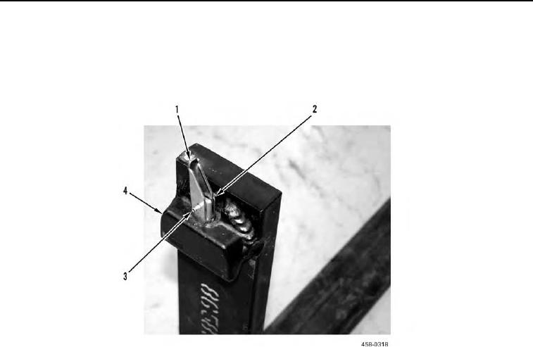
3. With assistance, press spring and pin assembly (Figure 7, Item 2) up against tine (Figure 7, Item 4) and align
holes in pin with holes in locking lever (Figure 7, Item 1).
4. Install roll pin (Figure 7, Item 3) in locking lever (Figure 7, Item 1) assembly. Test locking lever assembly for
correct operation.
Figure 7. Locking Lever and Roll Pin Installation.
0170