
TM 5-3805-292-23
0170
ASSEMBLY CONTINUED
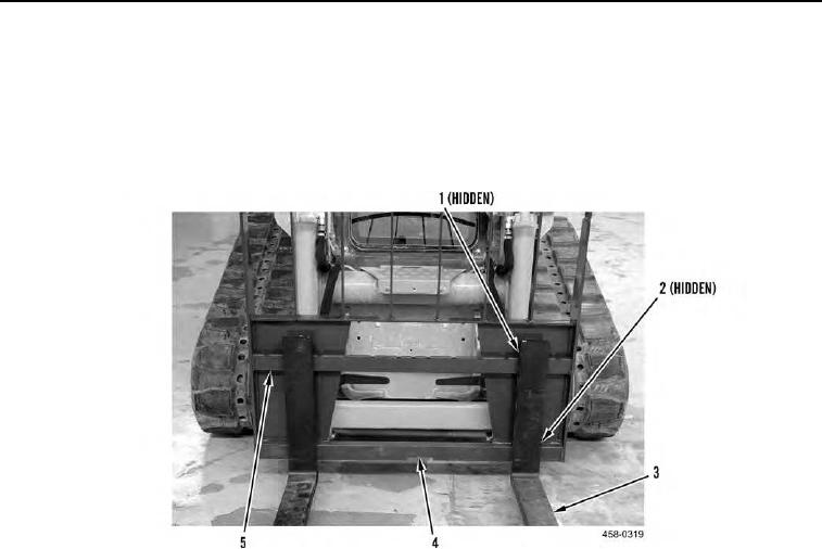
5. With assistance, raise end of tine (Figure 8, Item 3) and install upper retaining bracket (Figure 8, Item 1) of tine
on upper rail of pallet fork frame (Figure 8, Item 5).
6. Lower end of tine so lower retaining bracket (Figure 8, Item 2) of tine passes through notch (Figure 8, Item 4) at
bottom of frame.
7. Adjust position of tine to desired location and press locking lever (Figure 7, Item 1) to lock tine in place.
Figure 8. Pallet Fork Assembly.
0170
END OF TASK
FOLLOW-ON TASKS
000170
Verify correct operation of pallet forks (TM 5-3805-292-10).
END OF TASK
END OF WORK PACKAGE