
TM 5-3805-298-23-2
0155
Table 1. Kickout System Will Not Operate or Operates Improperly Continued.
0155
MALFUNCTION
TEST OR INSPECTION
CORRECTIVE ACTION
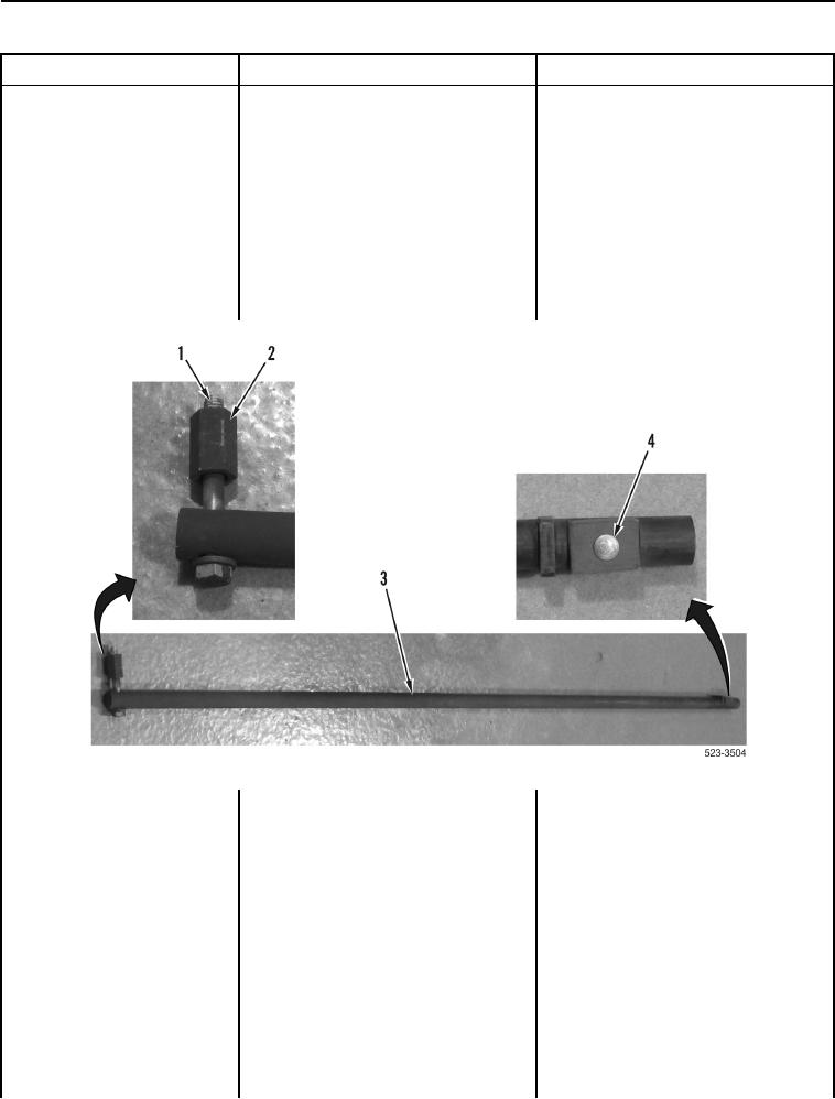
6. Inspect shaft (Figure 5, Item 3),
Kickout System Will Not
Shaft and Components OK Proceed
magnet (Figure 5, Item 4), bolt
Operate or Operates
to step 7.
(Figure 5, Item 1), and jam nut
Improperly - Continued
Shaft or Components Corroded or
(Figure 5, Item 2) for corrosion and
Damaged Replace shaft.
damage.
Proceed to Test Step 60.
7. Verify magnetic force of magnet by
Magnet Operates Proceed to Test
placing magnet (Figure 5, Item 4)
Step 7.
near machine surface.
Magnet Does Not Operate Replace
shaft.
Proceed to Test Step 60.
Figure 5. Shaft, Magnet, and Mounting Hardware.
0155
Test Step 7. Inspect Green (Power)
LED on Kickout Position Sensors.
1. Turn battery disconnect switch and
ignition switch to ON position
(TM 5-3805-298-10).
2. Set implement disable switch to
unlock position
(TM 5-3805-298-10).
3. Set kickout switch to ON position
(TM 5-3805-298-10).