
TM 5-3805-298-23-2
0155
Table 1. Kickout System Will Not Operate or Operates Improperly Continued.
0155
MALFUNCTION
TEST OR INSPECTION
CORRECTIVE ACTION
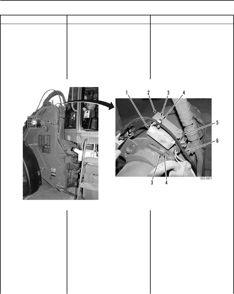
Test Step 5. Inspect Lift Kickout
Kickout System Will Not
Position Sensor Components.
Operate or Operates
Inspect lift kickout position sensor
Improperly - Continued
Kickout System Components OK
(Figure 2, Item 1), wiring harness
Proceed to Test Step 6.
(Figure 2, Item 6), mounting brackets
Kickout System Component(s)
(Figure 2, Items 2 and 5), bolts
Corroded or Damaged Replace
(Figure 2, Item 3), and washers
corroded or damaged kickout system
(Figure 2, Item 4) for corrosion and
components as necessary (WP 0297).
damage.
Proceed to Test Step 60.
Figure 2. Lift Kickout Position Sensor, Wiring Harness, and Mounting Hardware.
0155