
TM 5-3805-298-23-2
0155
Table 1. Kickout System Will Not Operate or Operates Improperly Continued.
0155
MALFUNCTION
TEST OR INSPECTION
CORRECTIVE ACTION
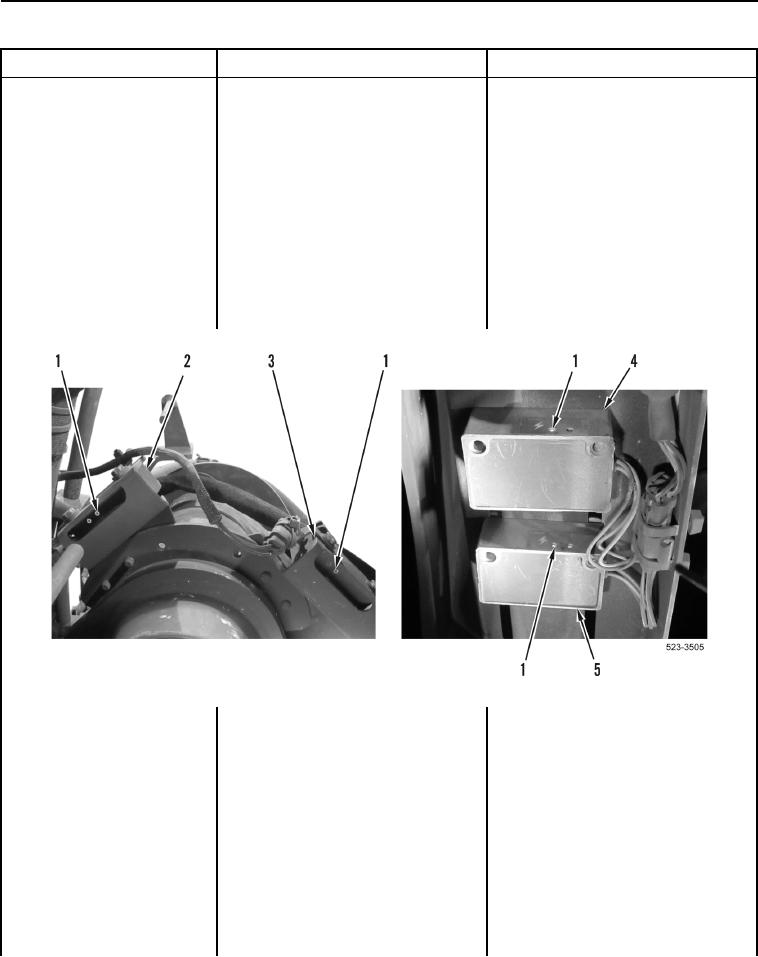
4. Verify green LED (Figure 6, Item 1)
Kickout System Will Not
LED Lit on All Sensors Proceed to
is lit on lift kickout position sensor
Operate or Operates
Test Step 8.
(Figure 6, Item 2), carry kickout
Improperly - Continued
LED Off on All Sensors Proceed to
position sensor (Figure 6, Item 3),
Test Step 22.
fork kickout position sensor
Bucket Sensor LED Off Proceed to
(Figure 6, Item 4), and bucket
Test Step 12.
kickout position sensor (Figure 6,
Fork Sensor LED Off Proceed to
Item 5).
Test Step 16.
Carry Sensor LED Off Proceed to
Test Step 20.
Lift Sensor LED Off Proceed to Test
Step 22.
Figure 6. Green (Power) LEDs on Kickout Position Sensors.
0155