
TM 5-3805-298-23-2
0155
Table 1. Kickout System Will Not Operate or Operates Improperly Continued.
0155
MALFUNCTION
TEST OR INSPECTION
CORRECTIVE ACTION
Test Step 13. Test Kickout Positioner
Kickout System Will Not
Wiring Harness for High Resistance
Operate or Operates
or Open.
Improperly - Continued
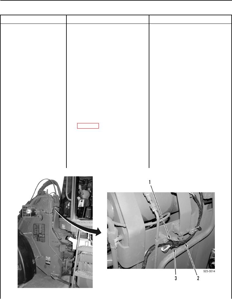
1. Remove tiedown strap (Figure 14,
Item 3) from wiring harness
(Figure 14, Item 2) and bracket
(Figure 14, Item 1). Discard
tiedown strap.
2. Disconnect connector LE-C5
(WP 0012, Figure 237) from
connector N-C1 (WP 0012,
Figure 238).
3. Connect jumper wire between
terminal 1 and terminal 3 of
connector N-C1 (WP 0012,
Figure 238).
4. Using digital multimeter
Resistance 5.0 Ohms or Less
(WP 0174), measure resistance
Replace front frame wiring harness
between connector N-C2 terminal
(WP 0301).
A and terminal C (WP 0012,
Proceed to Test Step 60.
Figure 233).
Resistance Greater Than 5.0 Ohms
Replace kickout positioner wiring
harness (WP 0297).
Proceed to Test Step 60.
Figure 14. Tiedown Strap.
0155