TM 5-3805-298-23-2
0155
Table 1. Kickout System Will Not Operate or Operates Improperly Continued.
0155
MALFUNCTION
TEST OR INSPECTION
CORRECTIVE ACTION
Kickout System Will Not
Operate or Operates
Improperly - Continued
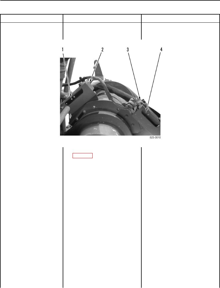
Figure 11. Testing Lift and Carry Kickout Signal Circuits to Pilot Valve.
0155
6. Using digital multimeter
Voltage Changes Accordingly for
(WP 0174), test for voltage
Both Sensors Replace pilot valve
between connector C-C22
(WP 0379).
terminal 3 and terminal 6
Proceed to Test Step 60.
(WP 0012, Figure 232) as follows:
Voltage Fails to Change Accordingly
a. Set bucket/fork switch to
for Bucket Kickout Position Sensor
bucket position (TM 5-3805-
Proceed to Test Step 39.
298-10).
Voltage Fails to Change Accordingly
for Fork Kickout Position Sensor
Proceed to Test Step 42.
b. Slide shaft (Figure 12, Item 4)
into channel (Figure 12, Item 3)
so that shaft magnet passes
over bucket kickout position
sensor (Figure 12, Item 5).
Yellow LED (Figure 12, Item 6)
will turn OFF. When yellow LED
is OFF, multimeter should
display 0L.

