
TM 5-3805-298-23-2
0166
AIR PURGE ON IMPLEMENT HYDRAULIC SYSTEM CONTINUED
9. Turn battery disconnect switch ON and start engine (TM 5-3805-298-10).
10. Engage parking brake (TM 5-3805-298-10).
11. Raise work tool from ground (TM 5-3805-298-10).
12. Tilt the bucket backwards and hold hydraulic controls in that position for 30 seconds (TM 5-3805-298-10).
13. Tilt the bucket level to the ground and lower the bucket to the ground (TM 5-3805-298-10).
14. Turn ignition switch and battery disconnect switch to OFF position (TM 5-3805-298-10).
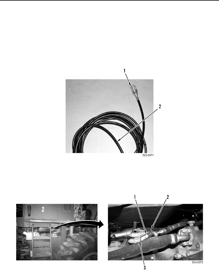
15. Disconnect female hose coupling (Figure 20, Item 1) from signal pressure connector (Figure 21, Item 1).
Figure 20. Hose Assembly.
0166
16. Install cap (Figure 21, Item 2) on signal pressure connector (Figure 21, Item 1) of pump pressure cutoff
(Figure 21, Item 3).
Figure 21. Signal Pressure Connector.
0166