
TM 5-3805-298-23-2
0166
MARGIN PRESSURE TEST CONTINUED
12. Remove right lower cab access panels and right ladder (WP 0347).
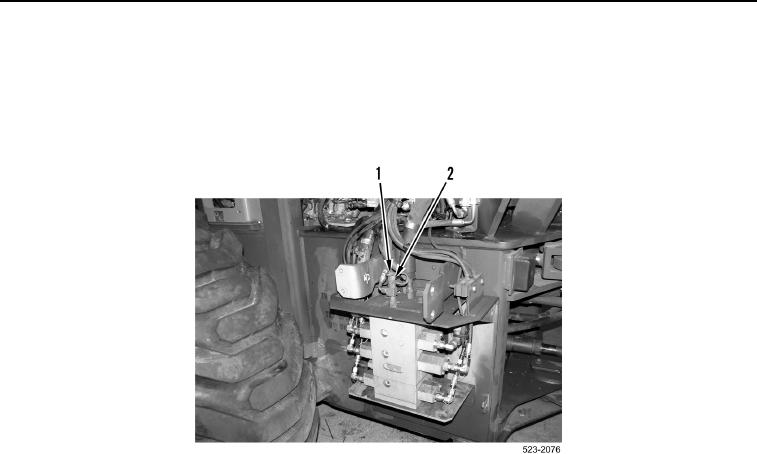
13. Remove cap (Figure 34, Item 1) from piston pump pressure connection (Figure 34, Item 2).
14. Connect other end of hose 177-7861 (Figure 33, Item 4) to piston pump pressure connection
(Figure 34, Item 2).
Figure 34. Piston Pump Pressure Connection.
0166
15. Turn battery disconnect switch ON and have an assistant start engine (TM 5-3805-298-10).
16. Have an assistant run engine at high idle (2,450 rpm) (TM 5-3805-298-10).
17. Have an assistant bring the hydraulic oil to operating temperature 140F (60C) (TM 5-3805-298-10).
18. Have an assistant raise bucket lift slowly (TM 5-3805-298-10).
19. Record the pressure on both gauges.
20. The difference between signal pressure and pump output pressure should be 290 15 psi (2,000
100 kPa). This is margin pressure.
21. If margin pressure is correct, proceed to step 22. If not correct, perform Margin Pressure Adjustment (in this
work package).
22. Have an assistant lower tool to the ground (TM 5-3805-298-10).
23. Turn ignition switch and battery disconnect switch to OFF position (TM 5-3805-298-10).
24. Install right lower cab access panels and right ladder (WP 0347).
END OF TASK