
TM 5-3805-298-23-2
0180
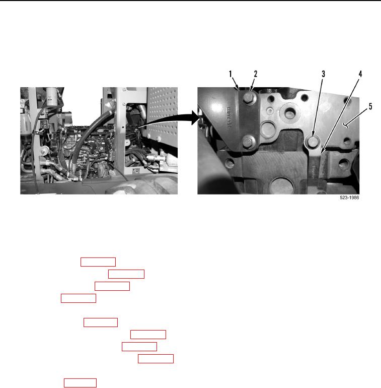
INSTALLATION CONTINUED
26. Install engine lift bracket (Figure 19, Item 1) and two bolts (Figure 19, Item 2) and on cylinder head
(Figure 19, Item 5).
27. Install bracket (Figure 19, Item 4) and bolt (Figure 19, Item 3) on cylinder head (Figure 19, Item 5).
Figure 19. Rear of Engine.
0180
END OF TASK
FOLLOW-ON TASKS
000180
1. Install fuel injectors (WP 0199).
2. Install valve cover and base (WP 0187).
3. Install exhaust manifold (WP 0197).
4. Install muffler (WP 0227).
5. Install coolant temperature sensor (WP 0248).
6. Install inlet manifold (WP 0196).
7. Install water temperature regulator (WP 0232).
8. Install secondary fuel filter base (WP 0221).
9. Install air cleaner housing and hoses (WP 0204).
10. Install engine ECM and bracket (WP 0265).
11. Install fuel rail (WP 0211).
12. Install hood (WP 0351).
13. Verify correct operation of machine (TM 5-3805-298-10).
END OF TASK
END OF WORK PACKAGE
0180-19/(20 blank)