Home
Download PDF
Order CD-ROM
Order in Print
Figure 14. Cylinder Head Bolt Tightening Sequence.
Figure 16. Heater Hose and Bypass Tube.
Field Maintenance Manual For 924H Wheel Loader -2
Page Navigation
676
677
678
679
680
681
682
683
684
685
686
TM
5-3805-298-23-2
0180
INSTALLATION
CONTINUED
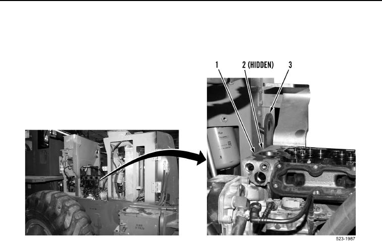
13.
Install
two
bolts
(Figure
15,
Item
2)
and
engine
lift
bracket
(Figure
15,
Item
3)
on
cylinder
head
(Figure
15,
Item
1)
.
Figure
15.
Front of Engine.
0180
0180-15